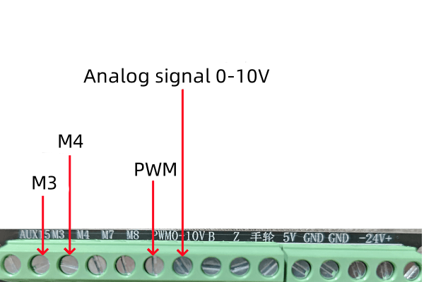
The ENC supports 0-10V analog voltage signal output for controlling the spindle speed of the inverter,
as well as M3 and M4 signals for controlling the spindle rotation direction of the inverter.
If you have a standard spindle (i.e., controlled only through a power switch), please refer to the relay control at the output port and use the M3 spindle switch port for control.
If it is a laser, connect the PWM signal and share the GND with the controller.
The relevant terminal positions are shown in the diagram below:
For VFD (Variable Frequency Drive) and spindle control, if you are new to this, we strongly recommend reading your VFD manual first. You should become proficient with using the VFD’s keypad to start/stop the spindle and adjust its speed before attempting to control it with an external controller. This is because simply wiring it according to our tutorial below is not sufficient; the VFD must be configured with the correct parameters for your specific spindle.
The wiring is very simple:
-
Connect the 0-10V from the controller to the FV port on the inverter.
-
Connect M3 from the controller to the Spindle Forward port on the inverter.
-
Finally, connect the GND from the controller to the COM terminal on the inverter.


